
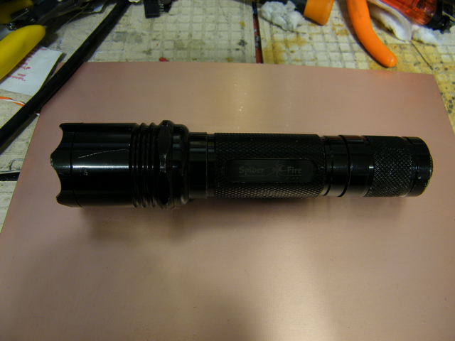
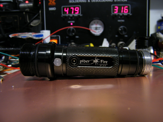
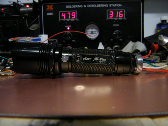
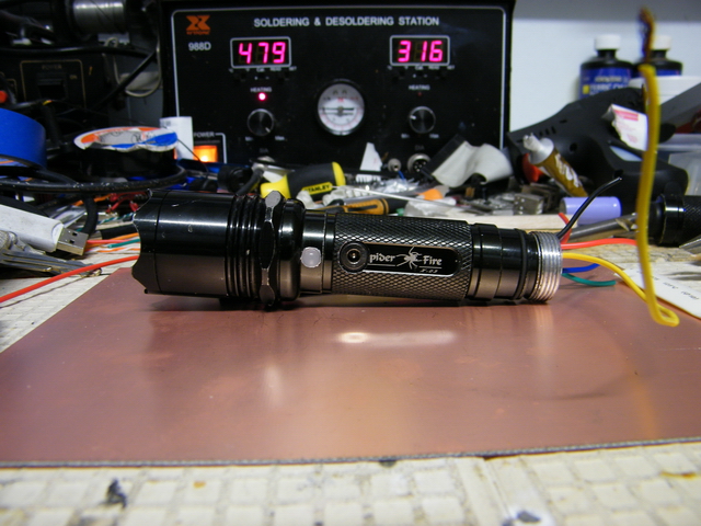
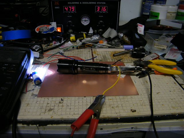
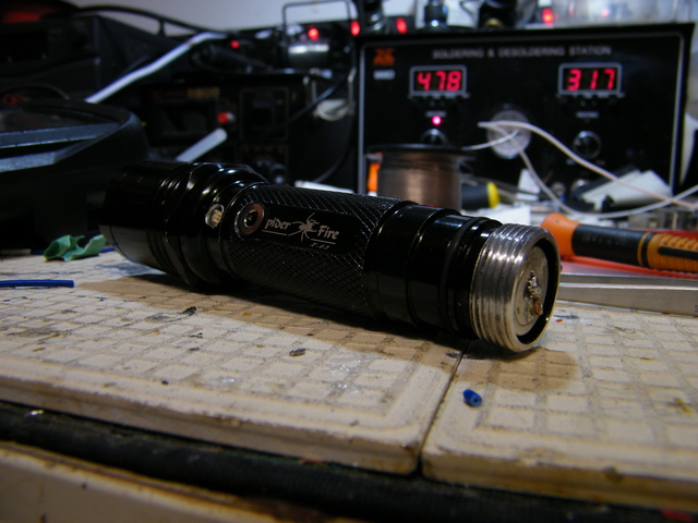
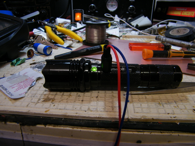
Here we have an AWESOME spider-fire CREE LED torch that's begging to be hacked.
It runs on TWO CR123A batteries and is freakin' expensive to maintain (here in Australia CR123's are about $9 each!) - Rather than simply buying a rechargeable set of batteries and a charger to suit, today we'll make it more portable by performing the following modifications:
Seriously. If you fuck up somewhere, you WILL set fire to something (I guess it's a win/win!) - Let us begin
[download] Parts List
[download] PCB artwork (Top Layer, 1:1 mirrored, print-ready, A4 page size)
[download] PCB artwork (Bottom Layer, 1:1, print-ready, A4 page size)
[download] Legend (Silkscreen / Assembly)
[download] Parts List
[download] PCB artwork (Top Layer, 1:1 mirrored, print-ready, A4 page size)
[download] Legend (Silkscreen / Assembly)
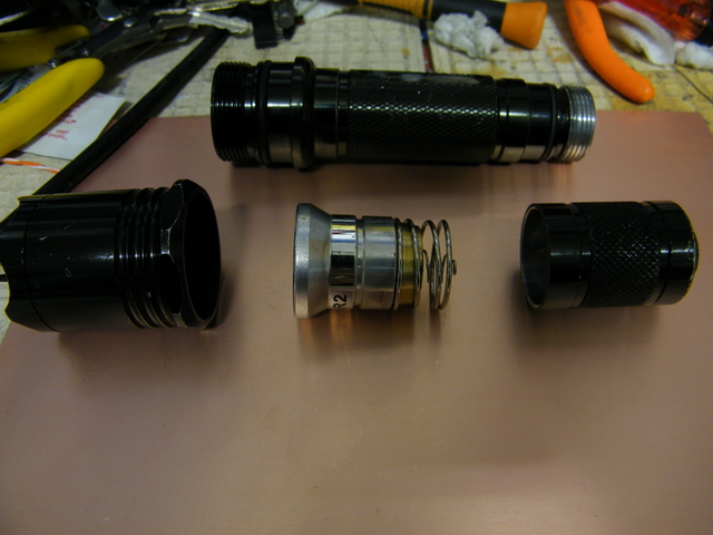
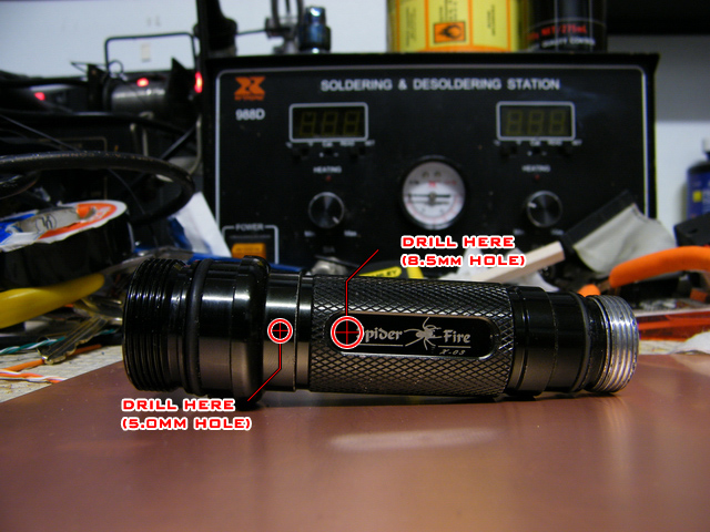
First we'll dismantle the torch into its key components. Unscrew the lens assembly and the lower spring / two way switch combo (no need to further dis-assemble these components)
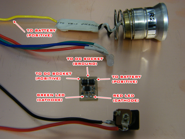
Now you'll need to drill two holes; one for the DC JACK (using an 8.5mm drillbit) and one for a 5mm LED (using a 5mm drillbit) - If you happen to have a 3mm tricolour LED on hand, or prefer to have seperate RED and GREEN LEDs, modify the aforementioned step to suit your needs. The recommended drilling locations are overlaid on the image below.
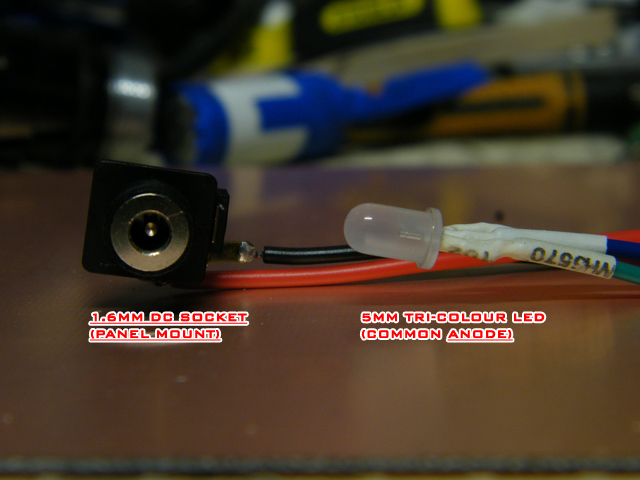
I honestly have no idea where I bought this 1.6mm jack from, but you can easily adapt the modification to whatever you have in your junk box - Simply solder and heatshrink some hookup-wire onto the LED and DC Jack. Leave the wires long, as we'll trim them to size later on
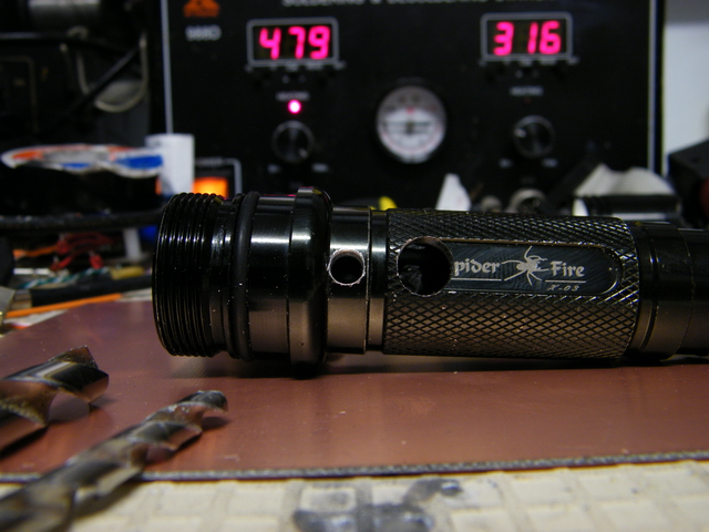
Testfit your DC jack and LED into the empty torch casing. The holes are only SLIGHTLY larger than the actual components, so it might be wise to use some needle-nose pliers when coaxing them into place, as you may have to introduce quite a bit of pressure (tweezers WON'T work, you'll just bend them!)
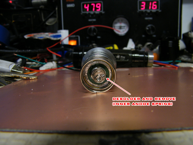
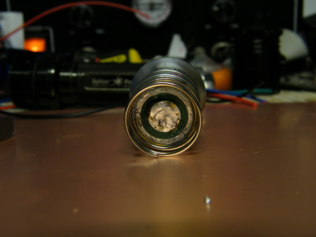
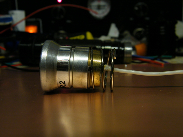
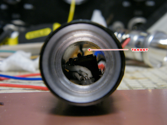
You'll need to remove the Anode spring from the CREE LED module then solder a wire in it's place. Simply heat the bottom of the spring with a soldering iron, and gently lift it off
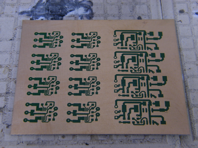
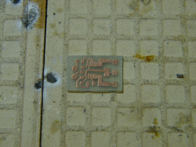
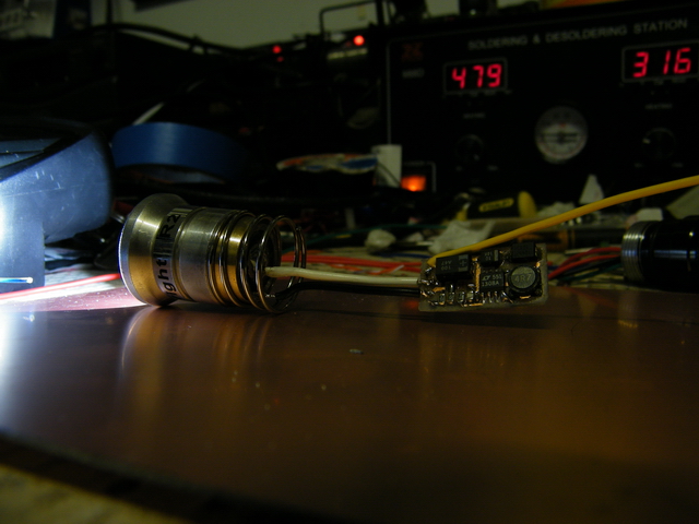
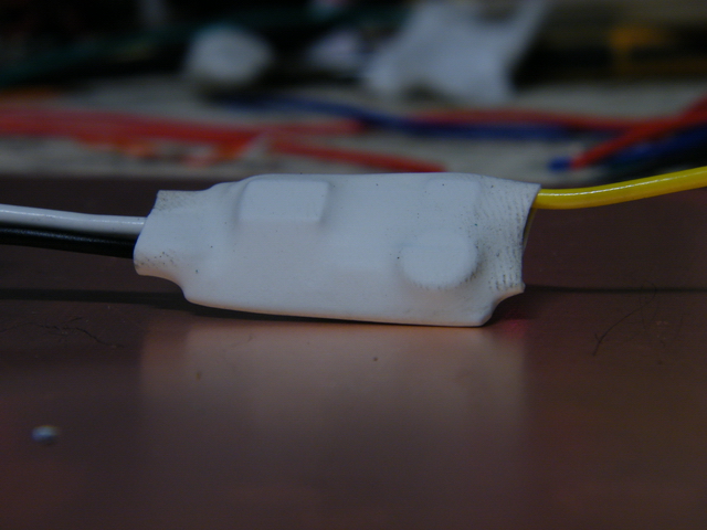
Etch and Assemble the Boost Converter and LiIon Charger PCBs :: Only the assembled LiIon board is shown below, but you should probably build both. I kept them as seperate PCBs in case you'd like to use either design in other projects (plus it's easier to squeeze two little boards into place, than one larger board)

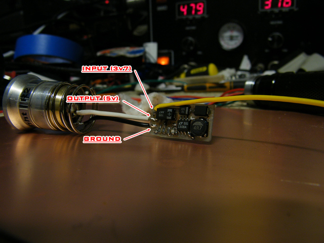
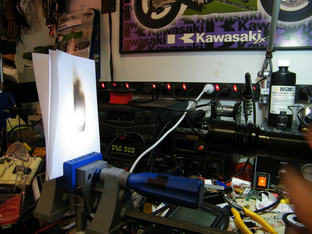
Now we'll set up and install the DC-DC boost converter, this'll step up our 3v7 battery to the 5v required to fully illuminate the CREE module.
As I mentioned before, the torch itself used to run on TWO 3v Lithium batteries. However after some testing, I found that alot of energy was wasted as the LED itself only requires 5 volts. The difference in current consumption between using two batteries and the boost converter circuit is 120mA.
After several trials using both supply types, I found (in practice), using the boost converter as opposed to a second battery only results in a 6-minute loss in the torch's usable time (58 minutes on average with two 3v batteries, 52 minutes on average using a boost converter with ONE 3v7 battery)
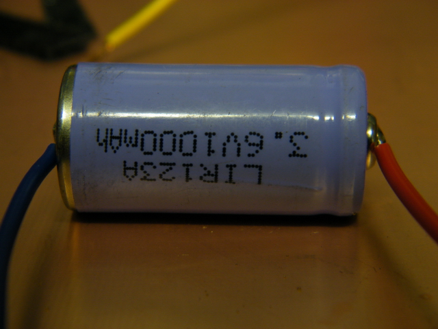
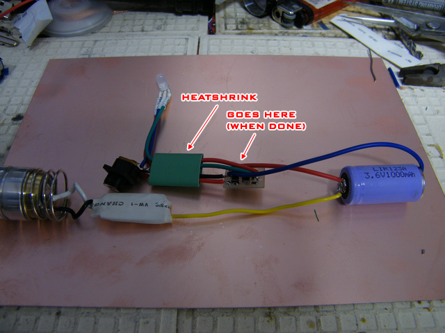
It's time to bring our entire circuit together. We'll start by soldering two wires to the LiIon battery (a little tricky at first), then follow through and cram everything into the case ever-so-gently.
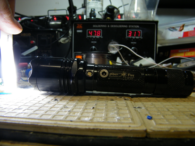
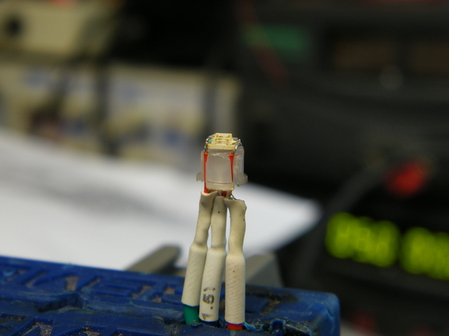
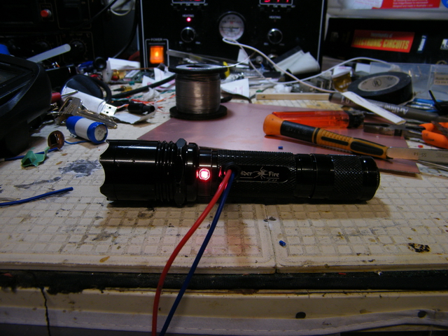
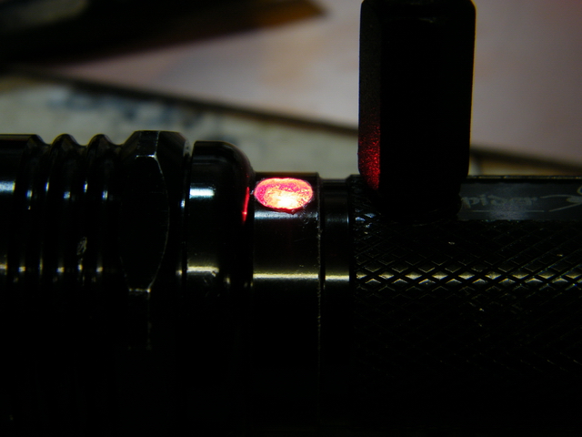
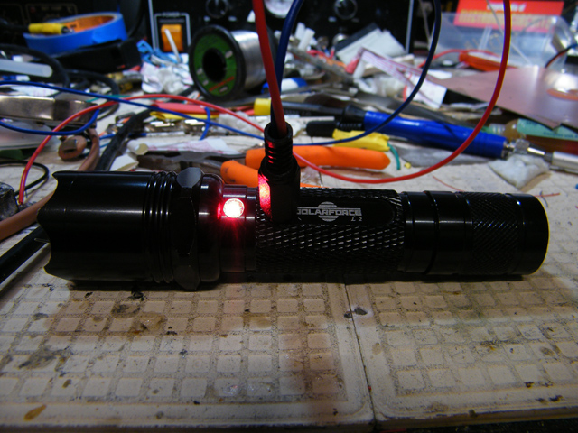
We know it works as a normal torch, but will it charge, or did we damage something during the installation? (I also fucked up, the triColour LED I used was common cathode, so I hacked it up and homebrewed a common anode version using an SMD LED and the remains of the 5mm tricolour LED)

Also modded my kid brother's "SolarForce" torch FLASHLIGHT this morning. Looks almost identical to my SpiderFire torch, so they're probably both knock-offs of another brand
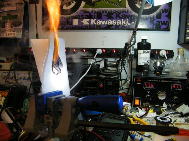
EDIT: It's been brought to my attention that the boost-converter circuit is operating in over-unity, that'd explain the fire in the images above! There may be a few reasonable explanations for this. My method of calculating the current consumption is flawed (simply measuring in series using a DMM, on both the input and the output), the samples for input and output current were taken too far apart (the CREE module draws less as it warms up), or, God did it.
I have no intention of misleading anyone; if anything here seems highly improbable, then it probably is.
-PodeCoet
Click here to get in-touch
 Modulated Arc Lighter