Update 13/09/12: Please don't build this design.
I threw it together using scrap parts. The MOSFETS are driven incorrectly and are working way beyond their intended specs, you need at least twelve in parallel with proper high-current drivers on the gates. It is prone to latch-up, and you can easily injure yourself due to constant malfunctioning. I've learnt alot in the three years since this has been posted, and this write-up is almost embarassing to keep posted online, it's only here to remind me of how silly I was
Update 02/12/09: The PCB LAYOUTS are now DOWNLOADABLE HERE
[Broken links fixed, 13/09/12]
Update 22/10/09: 10,000+ article hits per month and growing! Thanks everyone for your support.
Jiri has successfully replicated the welder design based on the schematic, with his own AWESOME modifications. He's posted the details onto his website (with source code included!)
As mentioned in the previous article, I only get a couple of hours a week MAX to update this entire site. As part of my income stems from the products I [used to] sell here, I'm forced to prioritise store updates and order shipping - Coupled with my day job at [censored], order shipping, studies and private work, I get absolutely swamped.
Hooray! Writing this means I've finally managed to complete the battery tab welding portion of my capacitive discharge design. In case you missed Part 1 of this write-up, check it out here. It'll give you a basic run-down of what the project is about as well as an overview of the hardware involved.
A couple of notes before we begin, skip everything else if you must, but please read the following few paragraphs.
Firstly Fritz9111 (Website here, Youtube channel here) was my initial inspiration behind this project. I watched his spot-welding video on Youtube a few months back and immediately fell in love with its design; He's recently uploaded the schematics / board artwork, and it's definitely worth checking out as both our designs are fundamentally different - It's only fair that he gets a plug for coming up with the idea initially.
Finally (angry mode *on*). I've taken the time to create the Schematics, revised PCB artwork and a labour-intensive Bill of Materials for you - In return I ask you not to be an addition to the five or so absolute wankers to abuse me using the contact form (specifically about not releasing the sources, I have my reasons) - I'm sure alot of you have encountered such beings elsewhere, in short they have absolutely no respect for anyones time but their own. To them, free/open designs should be "bug free" and work exactly to their expectations so they can use it for their thesis, otherwise it "sucks" and the author is a washed up hack. Dead-set, this isn't a joke, I've received quite a few emails with those exact words.
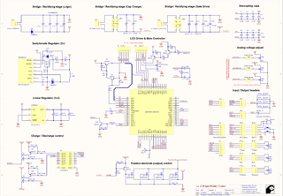
... And now without futher ado, here are the shematics / sources of the design which you've all repeatedly requested! Currently only the Schematic, BOM and Artwork have been completed, the firmware will probably never be released at this rate.
 Schematic diagram: PDF Format, 340KiB |
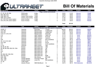
 Bill of Materials: PDF Format, 101KiB |
Note that all the part numbers in the bill of materials are hyperlinked to the suppliers product page (most are Australian sources, sorry guys!) - I created this rapidly using leftover parts from previous projects, so it's by no means the cheapest or most efficient use of components, and probably a terrible design.
Update: Thanks Jiri for pointing out an error with the IRFP2907 Source/Drain configuration!
Update 02/12/09: The PCB LAYOUTS are now DOWNLOADABLE HERE!
All further development for this project has been cancelled, I cannot provide any support (except for simple questions) due to time constraints. Thank you VERY much for all your support and feedback guys, both the good and bad. Due to time constraints I may not be posting any new projects for a while.
To clarify some questions I've been getting via email VERY often:
Now that that's out of the way, I strongly recommend looking into Jiri's firmware (see his website) and also Fritz's new design (website here) if you'd like to build something similar. Hope this helps
All the best!
-PodeCoet
Need to get in-touch?
NB: Please, no more questions about posting the artwork/source/etc! I'm absolutely swamped, I can't always reply to such queries, will get to it as soon as I have time.