
WARNING
If you attempt this project, your classmates will think you're a nerd. You'll likely wind up getting your head flushed and/or balls greased.
A friend and I enrolled ourselves into College a couple of years ago, with the ultimate aim of obtaining an Advanced Diploma in Electronics and Communications. Our study path starts at Certificate III, ultimately progressing through to Certificate IV, Diploma, then Advanced diploma.
One of our core subjects in Certificate III was Digital Sub-Systems, which is essentially Digital Electronics 101 - In this class we mainly covered basic Logic gates, and how to chain and assemble various gates to perform more complex tasks (for example, gate-based de-bouncers, shift registers, latches, and so on)
Our final project was a classic 'Up Counter' circuit, based on a 74LS193 BCD counter, which was to be built onto a bread board. Extra marks could be obtained by including a 'count down' function, reset, a second display, and so on.
One of the students asked the instructor if he could submit the project on an Arduino instead of a bread board, to which he received a stern but amusing NO.
I figured it'd be fun to mess with the instructor's sanity by hiding a microcontroller inside one of the logic chips, and having it briefly flash (occasionally vulgar) messages onto the seven segment display when left idle
UPDATE 01/01/15:
Many of you have asked - While I received full marks for the project, the hack was unfortunately not discovered. On the up-side I got away with it, despite slightly messing up the displayed segments for the numbers 6, 7 and 9
We are currently on Summer holidays until the 26th of January - I've emailed a link to this page to the campus, and will post an update if I get a response (assumingit still exists by then, thanks Tony Maggot Abbott!)
UPDATE 02/01/15:
Got an out-of-the-blue response moments ago, "Thanks for the info and all the best" - absolutely no fucks given.
Code posted due to complaints about not posting code
We'll be physically removing the 'core' of an SN74LS47N display driver, and replacing it with a PIC16F1503 microcontroller.
The PIC firmware will emulate the functions of the original SN74LS47N, and also mess with the instructor's sanity by briefly flashing messages onto the display when left idle.
All designs are provided as freeware for non-commercial use
[Download] Schematic Diagram
[Download] Microcontroller pin assignments
[Download] Datasheet - SA555P Timer IC
[Download] Datasheet - SN74LS14N Hex Schmitt Trigger Inverter
[Download] Datasheet - SN74HC08N Quad 2-Input AND gate
[Download] Datasheet - SN74LS193 4-Bit BCD up/down counter
[Download] Datasheet - SN74LS47N BCD to 7-SEG decoder/driver
[Download] Datasheet - PIC16F1503 microcontroller
[Download] Firmware - Rev A (binary) *
[Download] Firmware - Rev A (source) **
* Rev A firmware displays 'HELLO', 'PENIS', 'ASS', 'BALLS' and 'POOP' after approximately 20 idle seconds.
** The code is exceptionally shitty, inefficient, uses ints instead of chars on occasion, "LOL he's using 8 bits to store 1 bit of data", etc etc.
If you're asking yourself why there's so much silicon for such a simple design (ie: unnecessary/redundant parts), all parts handed to us had to be used in some way.
I was lazy, so everything became a debouncer. Realistically using the 555 timer for auto-increment/decrement would've been awesome
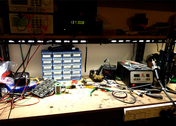
Ensure you start with a super-clean and sterile workbench

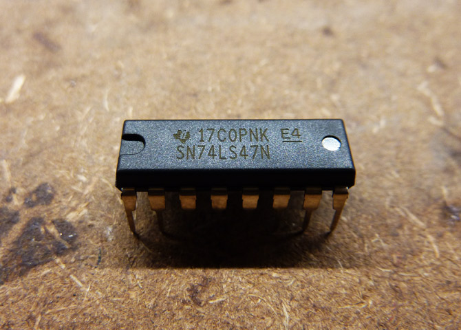
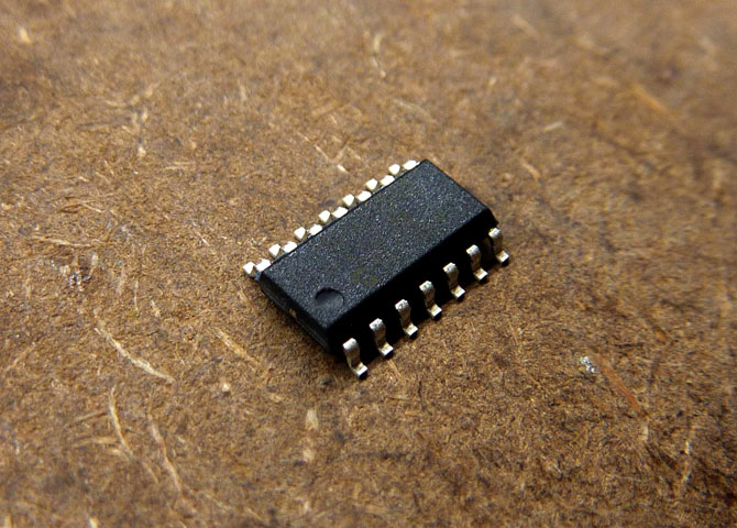
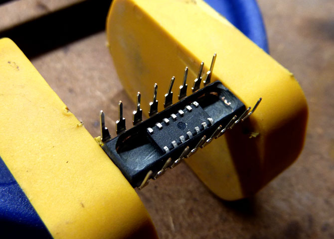
Prepare your anus SN74LS47N chip
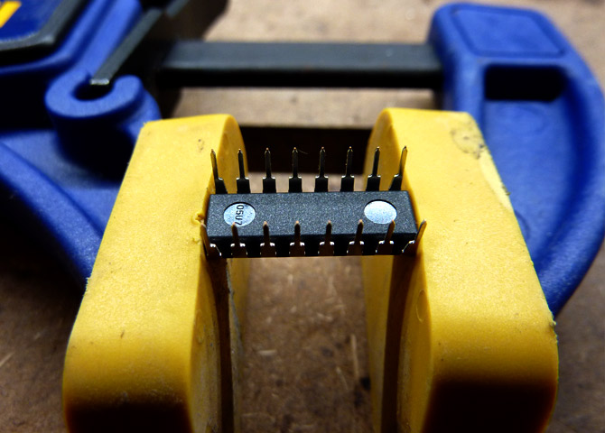
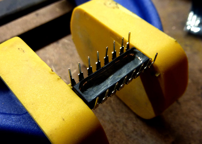
Place it into a vice-grip (or a plain vice, but vice-grips are preferred)
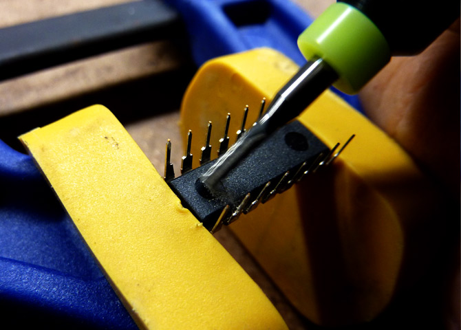
Carefully use a routing bit to route a cavity into the chip
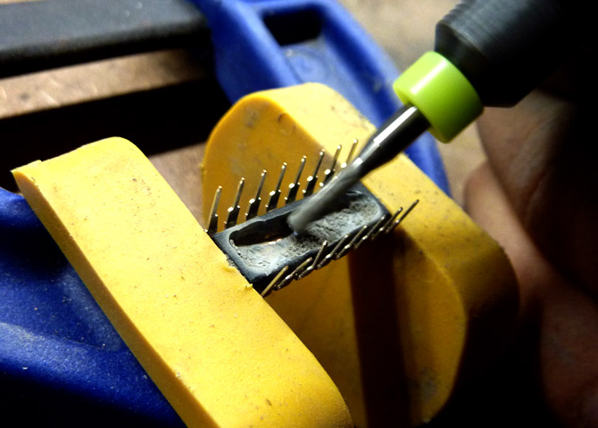
Keep routing until you get a nice rectangular cavity happening.
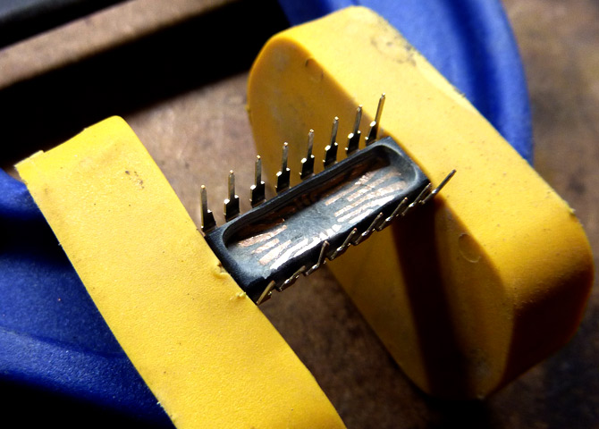
Looking good! We just need to go a little deeper so that our hack is hidden
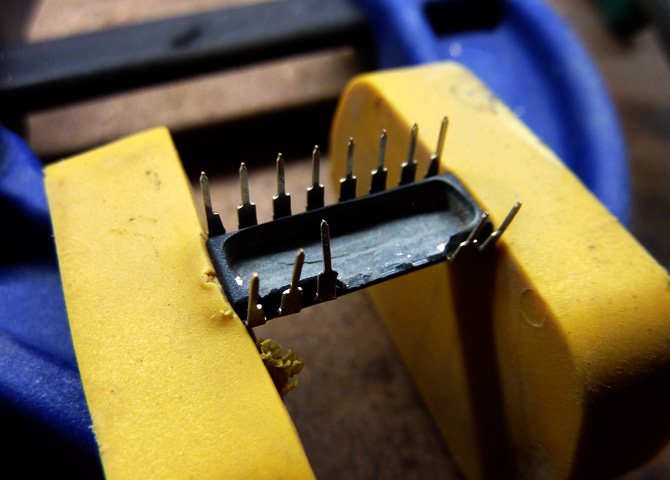
FUCK.
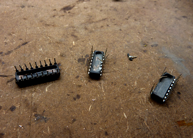
It's okay, we've only killed three so far.
Fourth time lucky.
Prepare the microcontroller
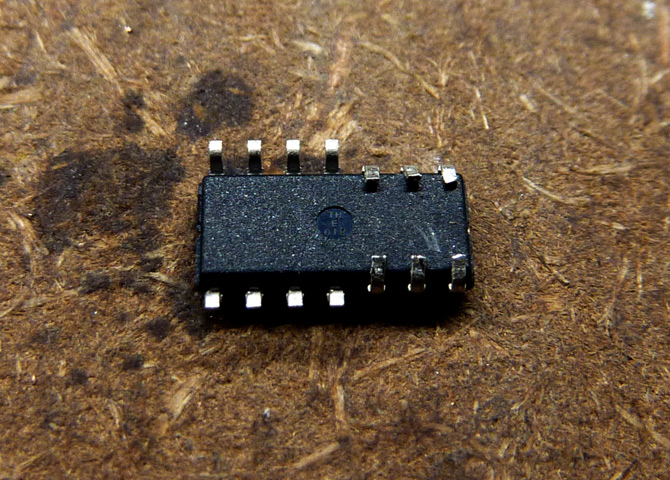
Flip it upside-down, and start bending the pins as shown
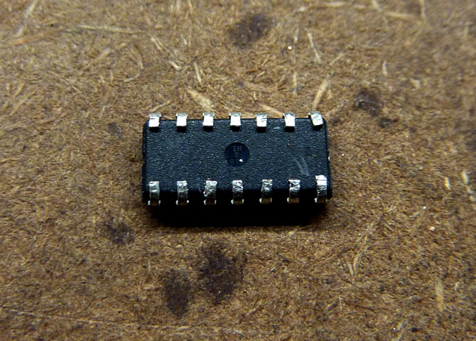
This is how it'll look with all the pins fully bent
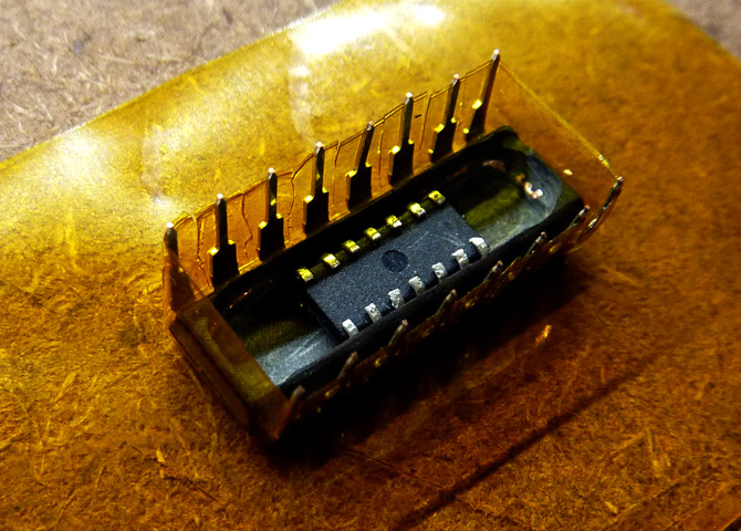
Apply some adhesive, and insert the microcontroller into the cavity (so that Pin 1 aligns with the 74LS47's notch)
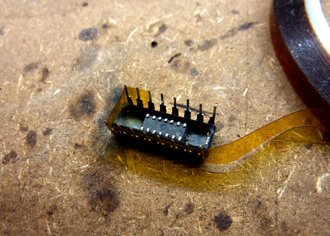
Wrap the pins in Polyimide tape - this will prevent the solder form 'wicking up' and foiling our plot (we need it to look factory stock at first glance)
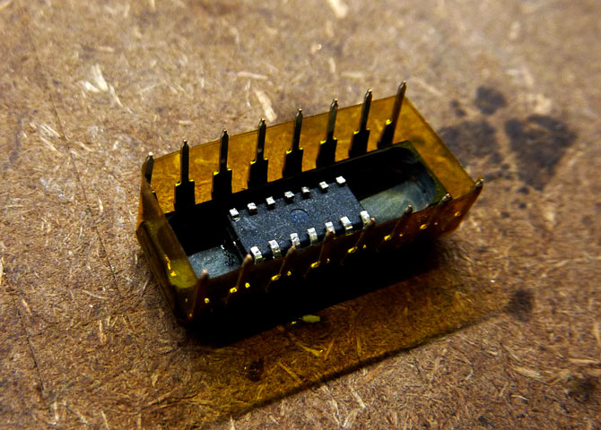
Post-mask shot, you only need one layer of polyimide, ensure it's stuck firmly onto all of the pins
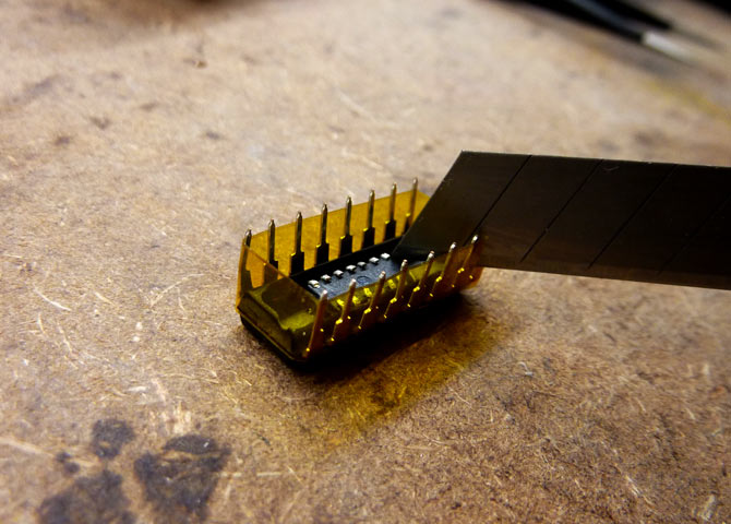
Use a sharp blade to slit the mask between the pins, this will make both removal and soldering much easier
We're now ready to start soldering!
Lightly tin the pins of the micro-controller
...And also tin the the SN74LS47 pins (lightly!)
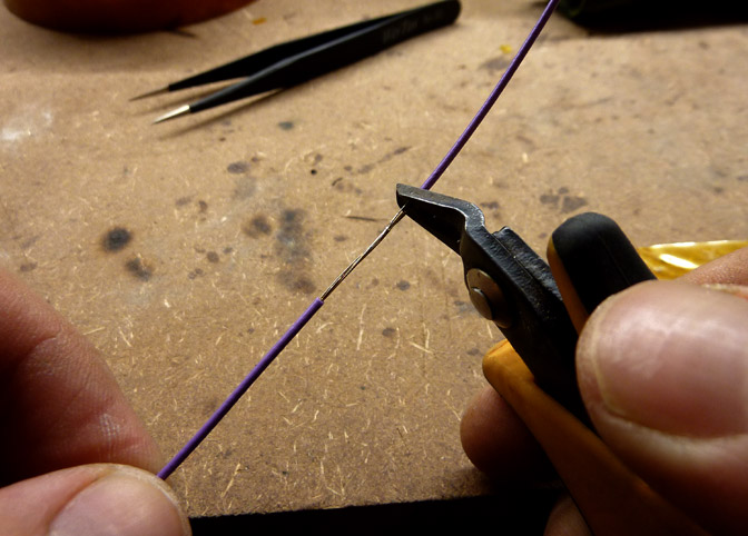
Remove the sheath of some fine hook-up wire
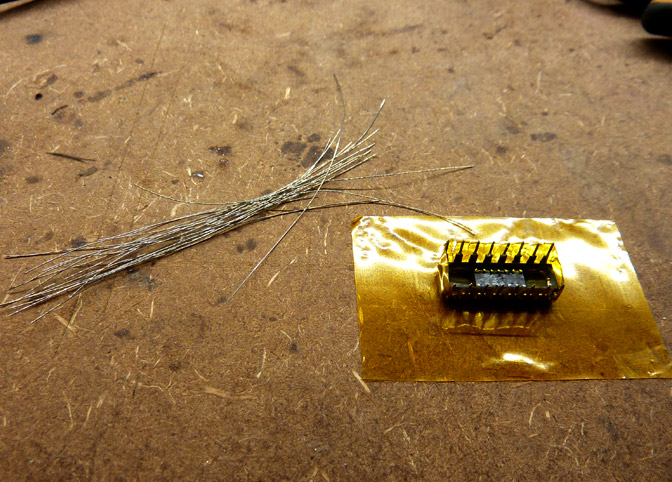
Pile the wire (within reach) onto your filthy bench
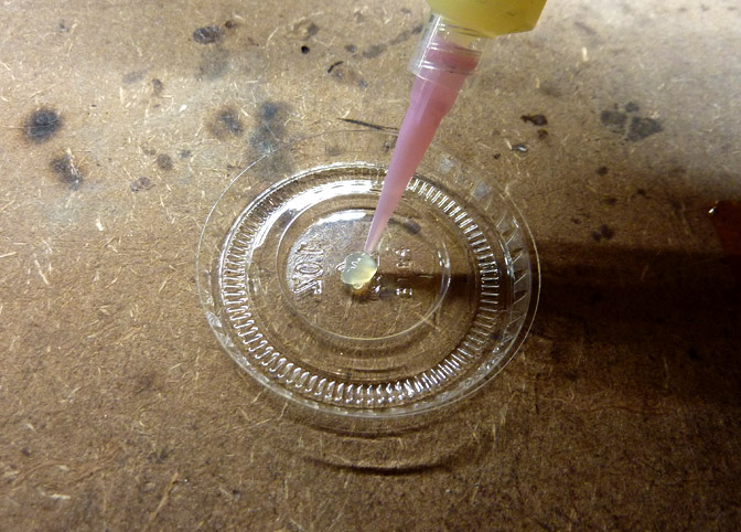
Squirt some paste flux onto something disposable
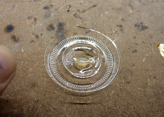
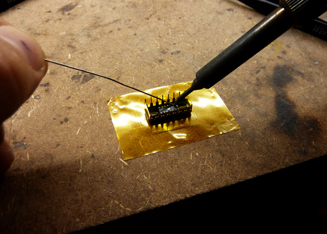
Dip the end of a wire into the flux
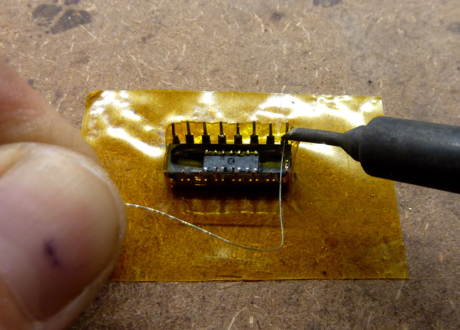
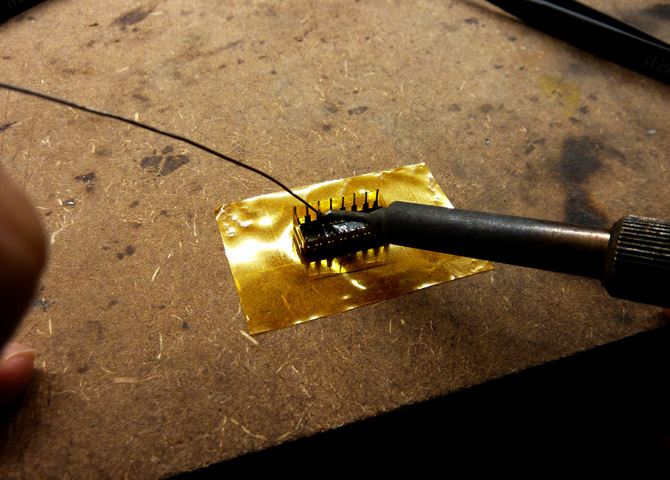
Solder said wire onto one of the IC pins
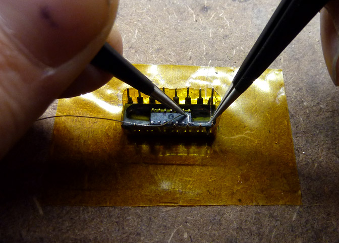
Carefully use a pair of tweezers to form the wire, and solder it in place
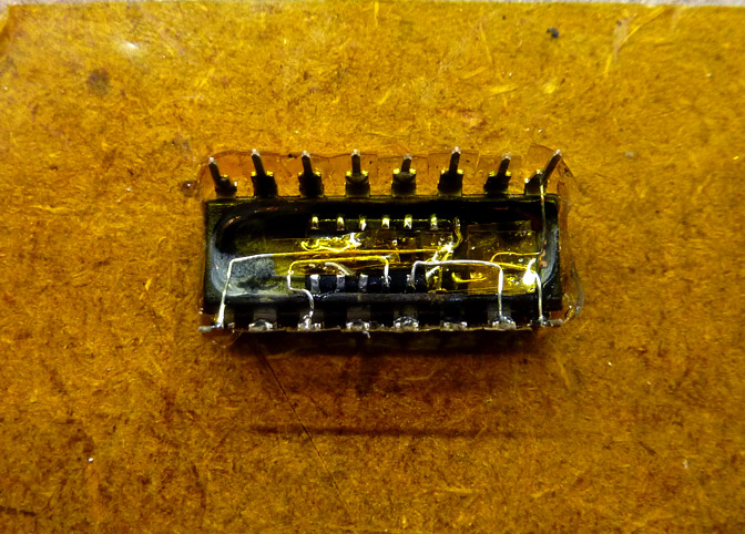
Halfway there, you can use bits of Polyimide to insulate wires from one-another
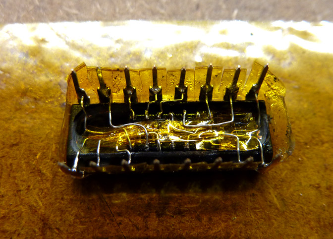
Wiring is completed, lots more Polyimide than expected
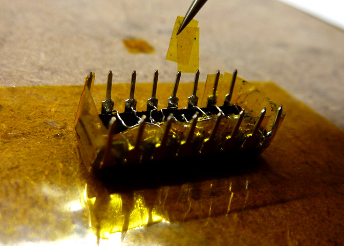
Use tweezers to remove the Polyimide from each pin
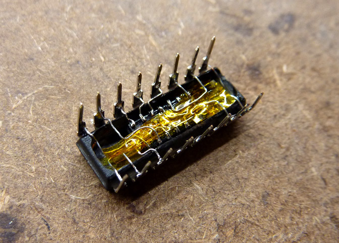
How it looks with all Polyimide removed
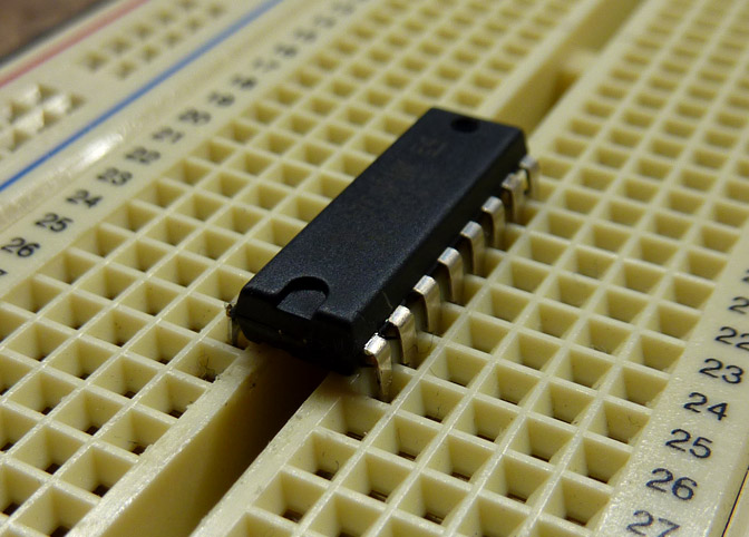
How it looks on the bread board (almost stock!)
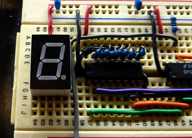
How it looks in-circuit
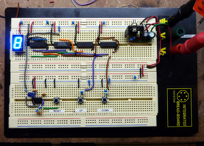
The completed circuit
Stay safe!
-PodeCoet
Click here to get in-touch or check out my other write-ups
 Modulated Arc Lighter