
Update 30/08/09: This is now a two-part article. The second part, which contains the Schematic, Artwork and Bill-of-Materials can be found here. It's still a work in progress as I only get a couple of hours a week to update this site, so apologies in advance.
EDIT: Welcome HackAday.com viewers! Before we begin, a quick quote from your comments section, from a guy that apparently needs a little more fiber in his diet:
Wow. That doesn't sound anything like me at all. I actually wanted to wait until this projects completion before posting it (along with all relevant sources) to hackaday, as I did with my previous Rechargable CREE LED Torch project. Evidently someone else found it interesting enough to post in its incomplete state, so I'm sorry.
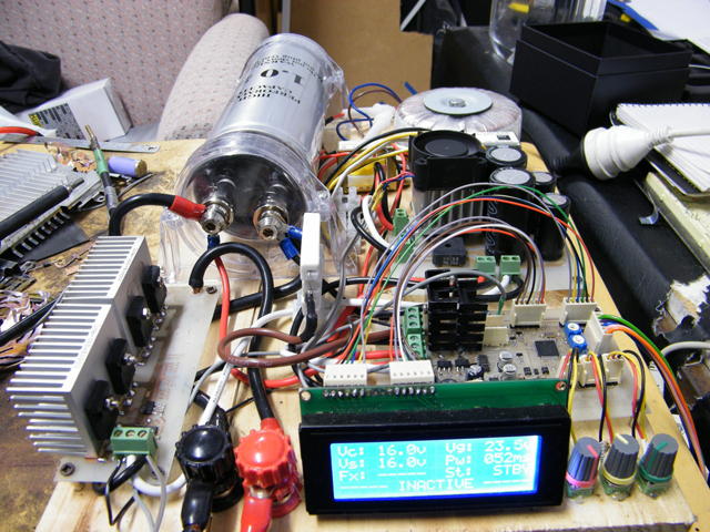
Moving forward, I've been working on a cheapie capacitive-discharge spot-welder for battery tabs over the past couple of weeks, during time off work for various reasons. I was inspired by a few youtube videos, and figured I had alot of parts left over from previous projects. The result was my first prototype below:
The design is broken down into the following five key segments (in no particular order):
For simple discharge-cutting, the controller can be left out, just as the cheerful lad from hackaday stated. Simply connect the audio capacitor directly to a high-current rectified DC supply (within the capacitors specs of course!) and use a switch or signal source (squarewave / etc) along with MOSFETs/drivers to turn the discharge on and off, or control the duty cycle and frequency. Under no circumstance leave out the ability to switch the output, especially if you use a high-current charging supply (you will blow your rectifiers and/or smoke your transformer if the electrode gets stuck!)
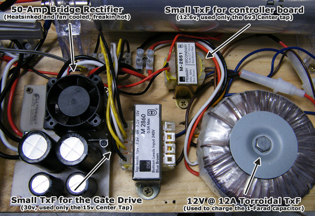
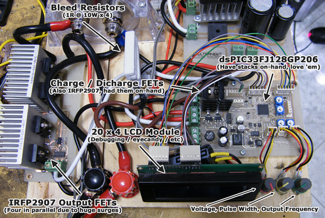
A breakdown of the segments can be seen below. I elected to use seperate power supplies to avoid noise / surges (and I had all these transformers lying around anyway!):
How it works: Power control
The 1-Farad capacitor is connected to its charge source (~16.5VDC) via an IRFP2907 MOSFET, as will as a discharge source (GND) via IRFP2907 MOSFET attached to 4 x 1-ohm 10-watt resistors in parallel. The voltage control method then becomes trivially simple.
I've set the dsPIC to sample all relevant analog voltage sources at approximately 250Hz. The sources I'm monitoring are the following: Voltage, Pulse Width and Frequency trimpots. The MOSFET Gate Drive voltage, the Capacitor voltage and finally the Charge voltage. 250Hz is quite slow, but well within the range of our requirements (since the capacitor takes quite some time to fully charge at 12amps, nearly 2500ms)
Now all we need to do is switch the charge MOSFET on or off relatively quickly, and do a comparison between the desired voltage and measured voltage of the capacitor. If the measured voltage is LOWER than the desired voltage, turn the charge MOSFET on. If the measured voltage is equal to or HIGHER than the preset voltage, turn the charge MOSFET off. See the code below for a simplified version of how it currently works (I know its messy!)
void __attribute__((__interrupt__, auto_psv)) _T2Interrupt(void)	// Interrupt routine, 250Hz
{
  if(getVolts < setVolts){		// If the measured voltage is less than the preset voltage
    chargePin=HIGH;			// Charge the capacitor
  } else {				// .. Otherwise ..
    chargePin=LOW;			// Stop charging the capacitor
  }
  IFS0bits.T2IF=0x00;			// Reset the interrupt flag
}
Here's the fun part. We also have a DISCHARGE MOSFET that we can use if the voltage gets too high. This also means you don't have to wait forever for the capacitor to discharge when you set a lower voltage (it'll take a few hours on its own, or about 30 seconds with a high-value bleed resistor) - so we append the following code (again simplified):
void __attribute__((__interrupt__, auto_psv)) _T2Interrupt(void)	// Interrupt routine, 250Hz
{
  if(getVolts < setVolts){		// If the measured voltage is less than the preset voltage
    chargePin=HIGH;			// Charge the capacitor
  } else {				// .. Otherwise ..
    chargePin=LOW;			// Stop charging the capacitor

    if(getVolts > (setVolts + 0.1)){	// If the measured voltage is greater than the preset
      dischargePin=HIGH;		// (plus a little extra), discharge the capacitor
    } else {				// .. Otherwise ..
      dischargePin=LOW;			// Stop discharging the capacitor
    }
  }
  IFS0bits.T2IF=0x00;			// Reset the interrupt flag
}
Let's review. We preset the voltage using a potentiometer. The code above checks to see if the measured voltage is less than the preset voltage. If it is, start charging the capacitor, if not, stop charging, and go to the next check. If the measured voltage is greater than the preset voltage (plus 100mV so we dont get into a loop), start discharging the capacitor, if not, stop discharging.
The above routine works extremely well, the voltage is matched to the preset voltage within 200mS, pretty much as quick as you can turn the potentiometer!
How it works: Output Control
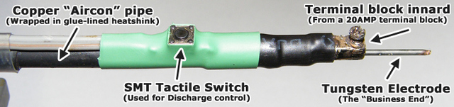
So far so good. You'll notice the probe (ie: discharge electrode) has a tactile switch on it. Alot of people use foot switches, but a) they're expensive, and b) I dont have any on hand. The tactile switch adds a nice touch either way.
To the point, without a microcontroller, the switch would simply attach between the GATE of the MOSFET array and the GATE DRIVE voltage - this is primitive, but very effective if you simply want to blast through thin steel. Each time the switch is depressed, the MOSFETs fully enhance, and conduct current through the probe to your target - hopefully not killing you or anyone else in the process.
Since we're using a microcontroller-based design though, the microcontroller will act like a proxy between the tactile switch and the MOSFETs. When the switch is pressed, the microcontroller decides whether to turn the MOSFETs on or off (or pulse them). This is a VERY powerful feature, as you're now potentially able to control the duty cycle, output frequency, pulse width and voltage at the probe. The code for this is also quite simple, provided you work out how to count in milliseconds using timers on your microcontroller (much much trickier that it first sounds!)
Once again, here is some code for you to analyse and probably harass me about. This is similar to what I use, except I have alot of additional flags and inconspicuous variables that will do nothing but confuse you. The code below adjusts the frequency of the output using the setting of the potentiometer, and is fixed at 50% duty cycle. It's just an outline, you can use a similar routine to control duty / pulse width, and probably shouldn't be copy/pasted since the frequency calculation is inverted for readability's sake:
void __attribute__((__interrupt__, auto_psv)) _T3Interrupt(void)	// Interrupt routine, 1000Hz
{
  if(buttonPressed){			// If the tactile switch is pressed
    if(freq==presetFreq){		// is freq equal to the pots frequency setting?
      output!=output;			// If yes, toggle the output (if off, turn on, if on, turn off)
      freq=0;				// reset freq so we can start counting again
    } else {
      freq++;				// If no, keep counting
    }
  } else {				// If the tactile switch is not pressed
    freq=0;				// reset freq so we can start counting again
    output=0;				// make sure the output is off
  }
  IFS0bits.T3IF=0x00;			// Reset the interrupt flag, or the uC will catch fire.
}
I'm unsure if anyone else would find this as interesting or fascinating as I did, but when cutting thinner metals such as copper flashing using lower frequency settings, you feel more "friction" during the cut (which I guess is to be expected, but is nontheless cool) - This has the added bonus of producing very sharp, very accurate cuts with less jitter and overshooting. At higher frequencies, it's like a knife through butter, but any slight shaking of the hand causes cuts to become "aliased" and jittery.
Turning the above device into a spot-welder is (in theory) relatively simple, just clone the above interrupt service routine and tweak it to suit. Unfortunately I'm out of free time for this week. I will be posting the schematics, artwork and firmware for the above design as soon as I get the chance to bugfix everything (inlcuding the layout, which is heavily patched with wire), current ETA is a couple of weeks :(
I hope this has cleared up any misconceptions, and at least given you enough knowledge to go ahead and create your own spot-welder-from-hell
This article has been updated and is now in two parts. I've since started part two which you can view here - I will be posting PCB layouts, Schematics, BOM, everything except a COMPLETE firmware image for SAFETY reasons on that page (you can also read more about the firmware issue there!).
Thanks everyone for your support, I've received just over a hundred emails about this design since posting it here, it was a much needed kickstart for future projects.
-PodeCoet
Need to get in-touch?
 Modulated Arc Lighter