
Update: Sunday, October 2nd 2011 @ 12:09:144 AEST
THIS PAGE IS NOW OUTDATED!
Please see our updated tutorial here; None of the GBC Creative laminators available on the market today produce acceptable results. Please do not purchase GBC Creative laminators for modification, we've tried them ALL, and they all suck horribly.
Update: Friday, August 14th 2009 @ 02:01:11 AEST
This hack is for the GBC Creative laminators found in Australia and Europe only! For US/International modders, Fritz9111 has successfully modified your version of the GBC creative laminator and put together a set of photos for you, which I've uploaded here [broken link fixed, sorry!]. Aussies looking to use "cheapshit" laminators can probably use a similar mod to Fritz's, which utilizes a high temperature (mechanical) thermal switch.
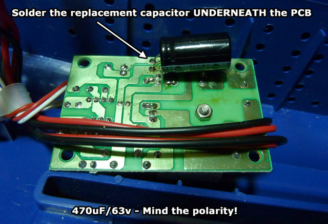
One additional step has been added to improve safety and reliability (replacing an Electrolytic cap with a higher voltage version, and shielding it from heat). Out of the 11 laminators I've modified, there has only been one issue to date concerning a leaky cap, so we might as well get this right the first time to avert headaches later on.
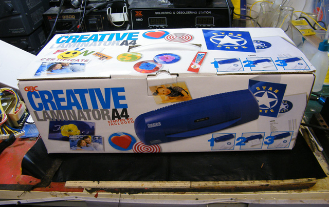
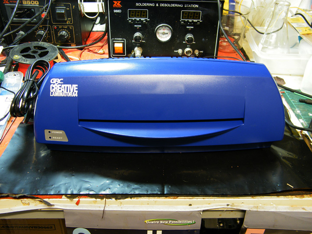
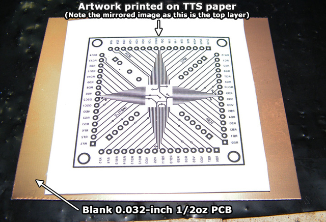
Today we'll be modifying a standard, cheap, readily available GBC Creative laminator for use in conjunction with PCB etching. While this article is specifically tailored for use with PulsarProFX products, it will work with pretty much ALL toner transfer methods (from magazine paper through to the Press'n'Peel!) - The only pre-requisite is the use of 0.8mm / 0.032in thick PCBs, such as the ones We/Mouser/Digikey/etc sell, in place of the regular 1.6mm / 0.064in thick PCBs.
Before we begin, ensure you've powered up the laminator FOR AT LEAST AN HOUR after purchasing. This is to wear the components in and to ensure there are no pre-existing faults. Also, note the following disclaimer (very VERY important information!)
Information about the upgrade
Pretty much all laminators (with the exception the the GBC Heatseal Hxxx series) are pre-set to a temperature range of between 105oC and 115oC to prevent damage to photos, toner-based print-outs, etc. Unfortunately for us, Toner becomes tacky at around 140oC and melts at a higher temperature still, rendering such laminators useless for toner-transfer-based etch-resist methods (which is why alot of you still use clothing irons for the transfer!)
As you no doubt have guessed by now, we're "upgrading" the laminator by increasing its working temperature, from the standard 115oC to 170oC, making it suitable for PCB fabrication. This is a relatively trivial task, and will probably work on most moderately cheap laminators. Really REALLY cheap laminators use a mechanical method of thermal control and probably won't work (just buy the damn GBC Creative laminator!)
You'll need the following items to perform the upgrade:
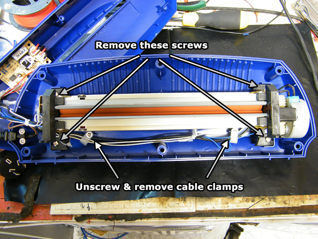
On with the article!

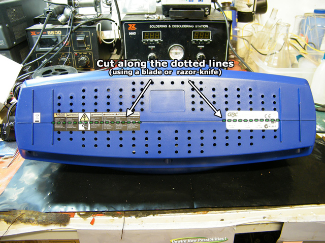
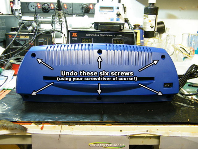
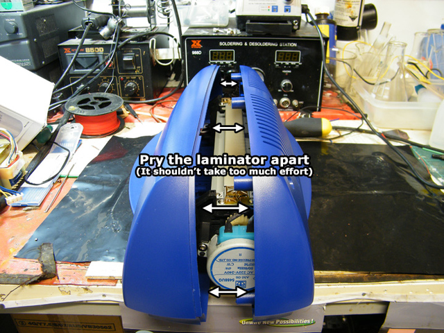
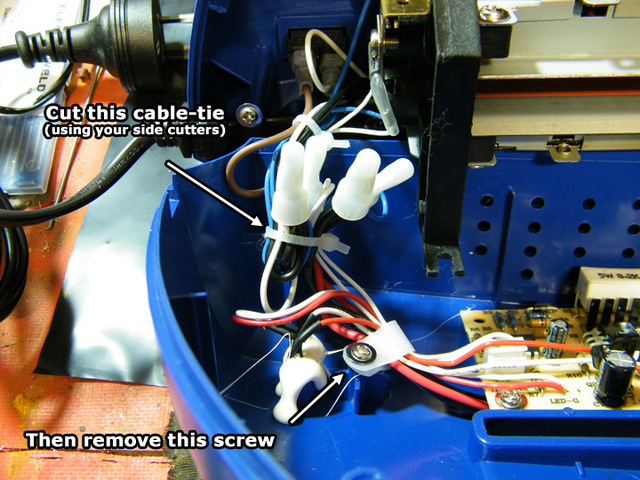
First modification complete!
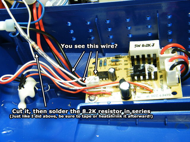
But what did we just do? To figure this out, you first need to understand how the circuit in the image above works. In a nutshell, it's a comparator (that is, a device that compares two voltages) and an NTC Thermistor (Thermistor being a resistor that changes value according to the temperature, and NTC meaning Negative Temperature Co-efficient, a fancy way of saying the resistance decreases with increasing temperatures)
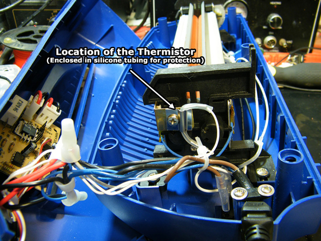
The normal resistance reading (ie: the reading at room temperature) of the thermistor in this laminator is approximately 200Kohms. The resistance at the "normal" operating temperature of this laminator (~115oC) is approximately 10Kohms. What we've done in the upgrade is add a further 8.2Kohms of resistance to the circuit. This means at ~115oC, the resistance is no longer 10Kohms, but 18.2Kohms!
I know, we're geeks right? Anyhow, this actually serves a very valuable purpose. At the time when the comparator in the circuit SHOULD think it's reached it's desired temperature of ~115oC, we've fooled it into thinking it's actually 55 or so degrees cooler than it really is. As a result, the heaters in the laminator are kept on until the temperature reaches ~170oC - AWESOME!
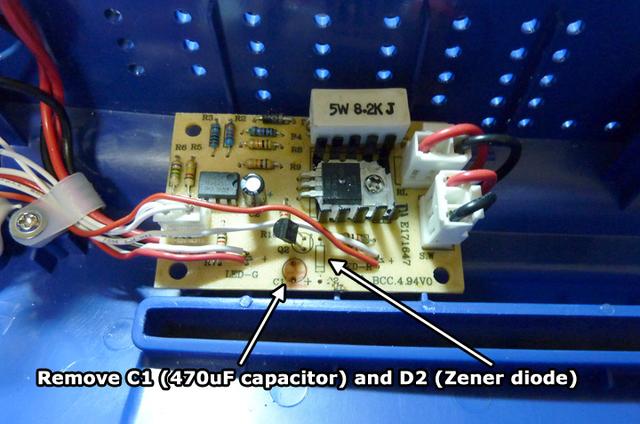
The second modification (replacing the cap and removing the diode) have a different purpose. The silly technicians at GBC used a 16V capacitor on a line that may reach up to 25-30V from time to time. To protect the capacitor against these voltages, they simply placed a zener diode in parallel to the cap. Well it turns out, these diodes have a habit of dying occasionally, and the capacitors leak/explode shortly afterward. We simply replaced the capacitor with a higher voltage version, and mounted it away from direct heating (as higher voltage caps are less tolerant to higher temperatures!)
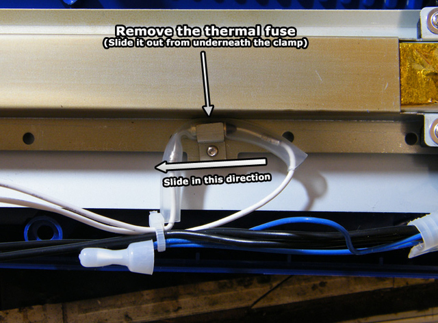
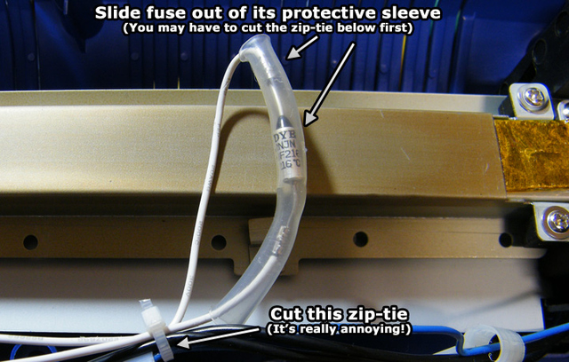
Now for the bad news. As with pretty much all devices containing heating elements, there are countermeasures for such hacks (actually it's purely for safety / overheating protection, but let's pretend we're cool for a second!) - The protective device in this case is a Thermal Fuse. Just like a regular fuse, this device literally dies and needs replacing when overload conditions are met. The only difference is a household fuse dies on over-current, whereas a thermal fuse dies on over-temperature
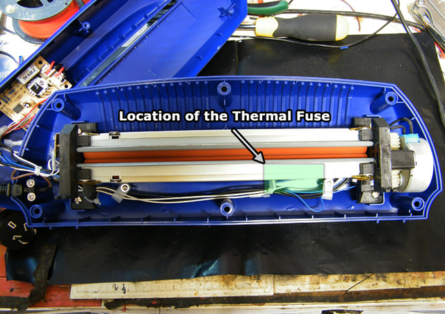
The rated temperature of the thermal fuse in this case is 216oC. But you're thinking wait a sec, the upgrade only increases the temperature to 170oC! So What gives? It turns out, due to the location of the NTC Thermistor, the reading it obtains is of the metal enclosure and not the heated rollers. Basically, the enclosure temperature is always higher than the roller temperature, until they reach an equillibrium (meaning, until the entire assembly reaches the same temperature all over)
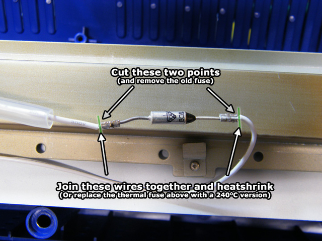
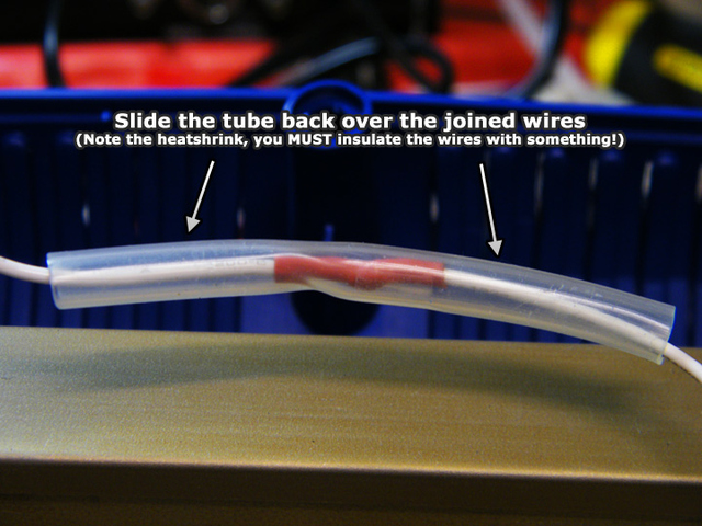
To fix this we'll simply replace the fuse with one of a higher temperature rating. The highest rating you can obtain (in the same package) is 240oC, though if you're lazy/dangerous like me, you can simply cut the fuse out of the circuit and join the wires. I highly, HIGHLY recommend buying a damn fuse though, as it's the only protection method available for the entire laminator -- Let's begin!
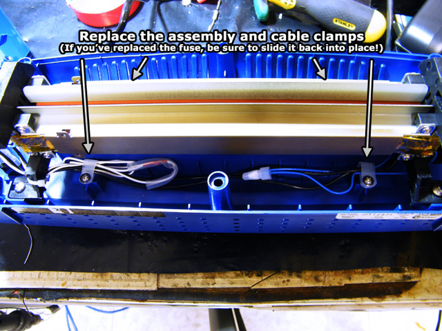

We're done!
You've just performed a $3 (or less if you've left out the thermal fuse) modification to a ~$50 laminator, successfully increased its operating temperature to 170oC and are now able to perform PAINLESS and FAST toner transfers, with sharpnesses and track widths you've never been able to obtain before!
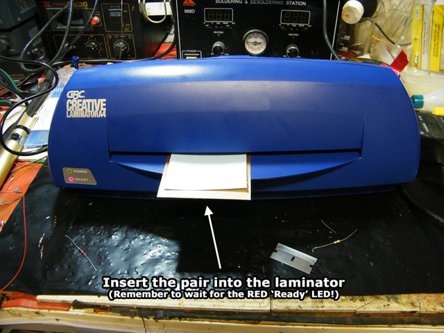
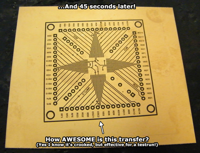
Not convinced? Let's do a quick SIMPLE demo using TTS PAPER (you can substitute this with Press'n'Peel, magazine paper, etc)
Check out our A-Z photo tutorial for PCB etching using the above modification by clicking here, or our Articles Page by clicking here
-PodeCoet
Click here to get in-touch!
 Modulated Arc Lighter